Plexus Connect - Charts view
Data displayed in both Plexus Connect grid and form views can be visualized using an integrated component called Charts view.
Currently, there are following types of charts available in Charts view:
-
Scatter plot - this chart allows one property to be plotted against another as a scatter plot. e.g. a plot of logP vs. PSA for a set of structures.
-
Histogram - this chart allows frequency distributions to be displayed as a histogram. e.g. a plot of the distribution of molecular weight or logP values.
-
Radar chart - this chart allows multiple properties to be visualized and compared. It is best suited for comparing properties of a small number of rows of data (e.g. a few selected molecules).
-
Box plot - this chart allows statistical characteristics to be visualized and compared. It is best suited for comparing properties among discrete smaller set of groups.
On this page:
Creating a chart
Data can be visualized from any given result set (e.g. an opened view or a loaded list). Click on the Charts ( ![]() ) icon within the navigation toolbar and select one of the available chart types you want to create. Fields containing values to be visualized are listed in dropdowns and can be selected by clicking. For each chart type, the dropdowns contain lists of fields available for visualization — e.g., for scatterplots, beyond to field selection for displaying values on axes, coloring, size and shape of data points is also customizable. Below the dropdowns for field selection, properties displayed in the Card can be selected in Additional fields section.
) icon within the navigation toolbar and select one of the available chart types you want to create. Fields containing values to be visualized are listed in dropdowns and can be selected by clicking. For each chart type, the dropdowns contain lists of fields available for visualization — e.g., for scatterplots, beyond to field selection for displaying values on axes, coloring, size and shape of data points is also customizable. Below the dropdowns for field selection, properties displayed in the Card can be selected in Additional fields section.
In the case of datatrees containing multiple entities, fields in dropdowns are arranged into entities. When a field is selected, the corresponding entity name appears next to the field name.
Using the Select field icon ( ![]() ) simplifies field selection. After clicking the Select field icon, a field for visualization can be chosen by clicking the preferred field in a widget of a form view, respectively, in a column of a grid view (table).
) simplifies field selection. After clicking the Select field icon, a field for visualization can be chosen by clicking the preferred field in a widget of a form view, respectively, in a column of a grid view (table).
In the opened grid or form view, the fields selected for visualization are highlighted with a red outline. They also appear in the Add new chart panel, independently on the way of their selection.
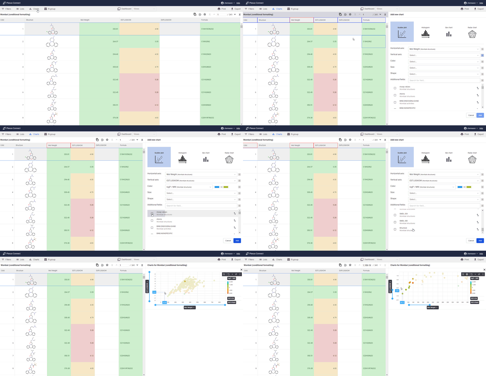
There are two options available in the dropdown menus of axis titles. The first one is for changing of Dimension Mapping. By clicking on this option, a scrollable menu opens. It contains a list of all fields available for selection and enables the user to restore the chart with the newly selected field. The second option is Change to log/linear scale. By clicking this option the axis scale switches from linear to logarithmic and back. For histograms, the second option in the dropdown menu enables customization of bin width.
The legend panel of the data point coloring is also scrollable and contains a list of all available fields. Switching to a new field changes the color scheme accordingly. Below the legend panel, the colors of the current color scheme and the values they represent are listed. Similarly, the data point size and shape are indicated on the corresponding legend panels. Both contain lists of all available fields, the analogous schemes of data point size and shape and the values they represent.
When the user hovers over a discrete value, an eye icon appears on the right. By clicking the eye icon, all data points corresponding to the selected value can be hidden/restored in the chart.
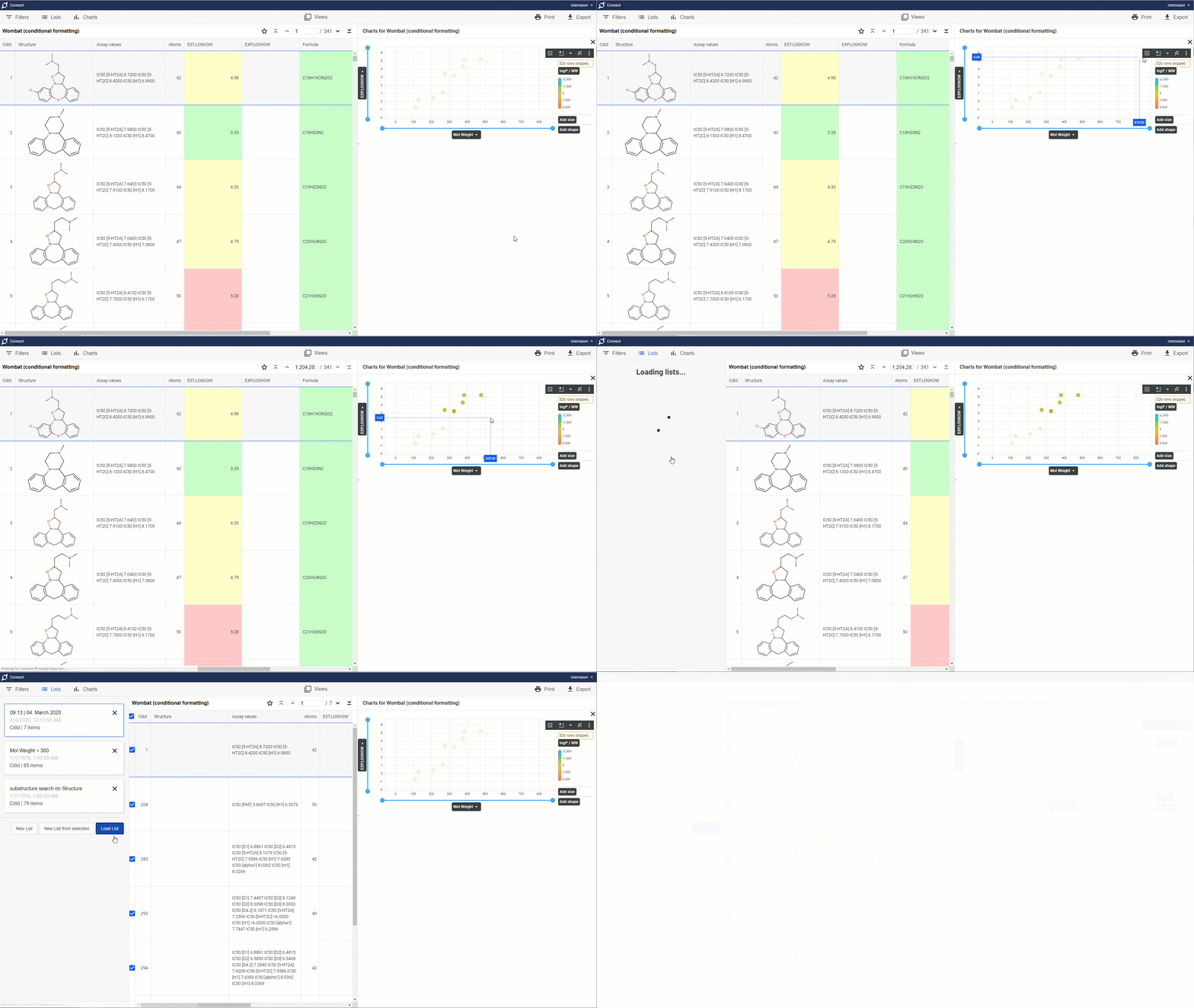
The single axis zoom tool (represented by blue lines along each axis) is available in scatterplots and histograms and provides additional navigation functionality. Moving one of the blue lines is used for scrolling. Changing the size of the blue lines by dragging one of their anchor points will zoom in/out the chart along the given axis.
Data selection
Data displayed in a chart are automatically synchronized with a corresponding view. This means that data selected in the chart are also selected in the view and vice versa. Selected data can be stored in form of list, by clicking on the Lists icon within the navigation toolbar and choosing New List from selection option. Selection can be done either within the view or within the chart by one of the available selection tools:
-
Rectangular selection
-
Rectangular deselection
-
Freehand selection
-
Freehand deselection
-
Cherry picking (selection of individual data points)
The selection tools for rectangular selection and deselection, freehand selection and deselection are available in the dropdown menu on the legend panel.
The cherry picking selection option is available by simply clicking on individual data points in the chart.
By clicking on the Deselect All icon on the legend panel, the whole selection reappears back to its default state both in the view and in the chart.
Curve fitting
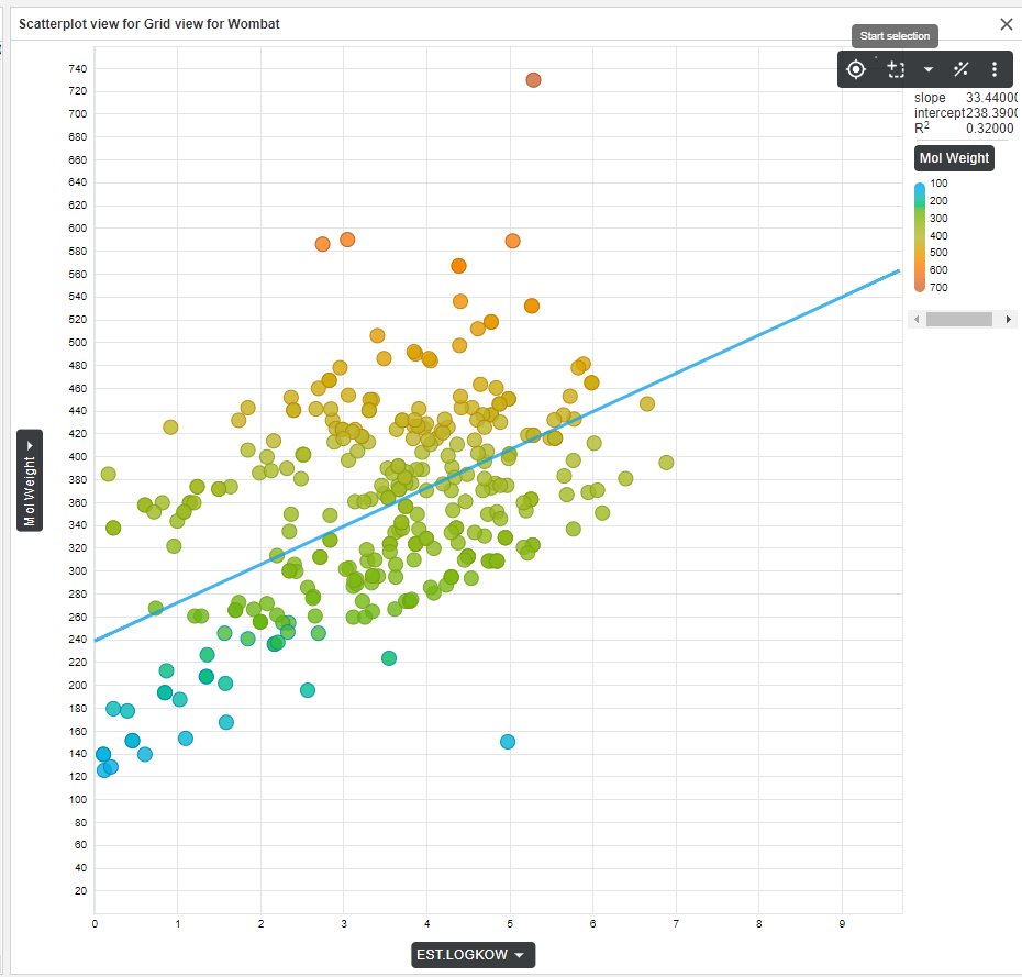
Several curve fitting options can be used to highlight trends in your data set. Click on the Add Regression icon on the legend panel to open an option menu and choose one of the following regression options:
-
Linear regression
-
4PL regression
-
Exponential regression
-
Power regression
-
Logarithmic regression
The corresponding regression parameters can be found under the legend panel. You can exclude any point from the curve fitting by rectangular or freehand selection or by selection of individual data points. On that occasion the regression curve will be recalculated and the regression parameters will be adjusted and displayed.
Saving a chart
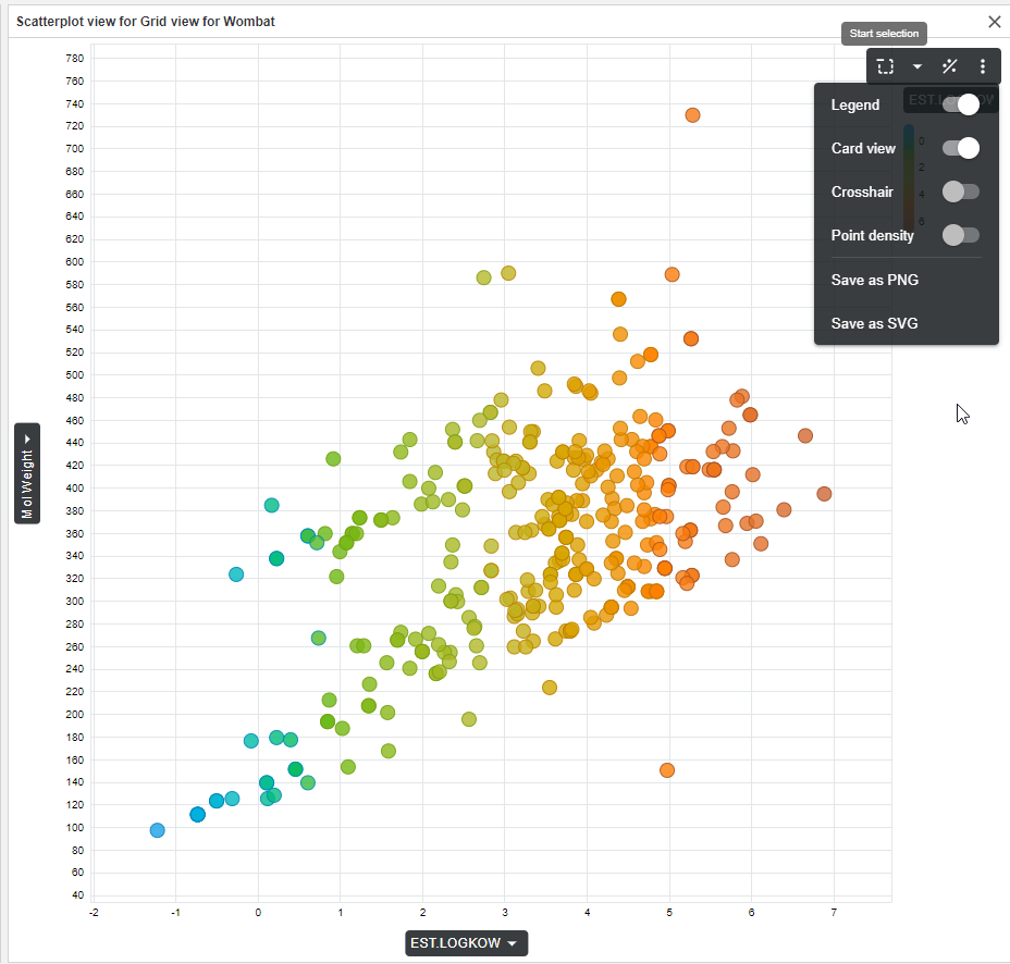
The chart can be saved as PNG or SVG file. This functionality is available by clicking the menu option on the legend panel.
Scatter plot specific options
Hexbin view
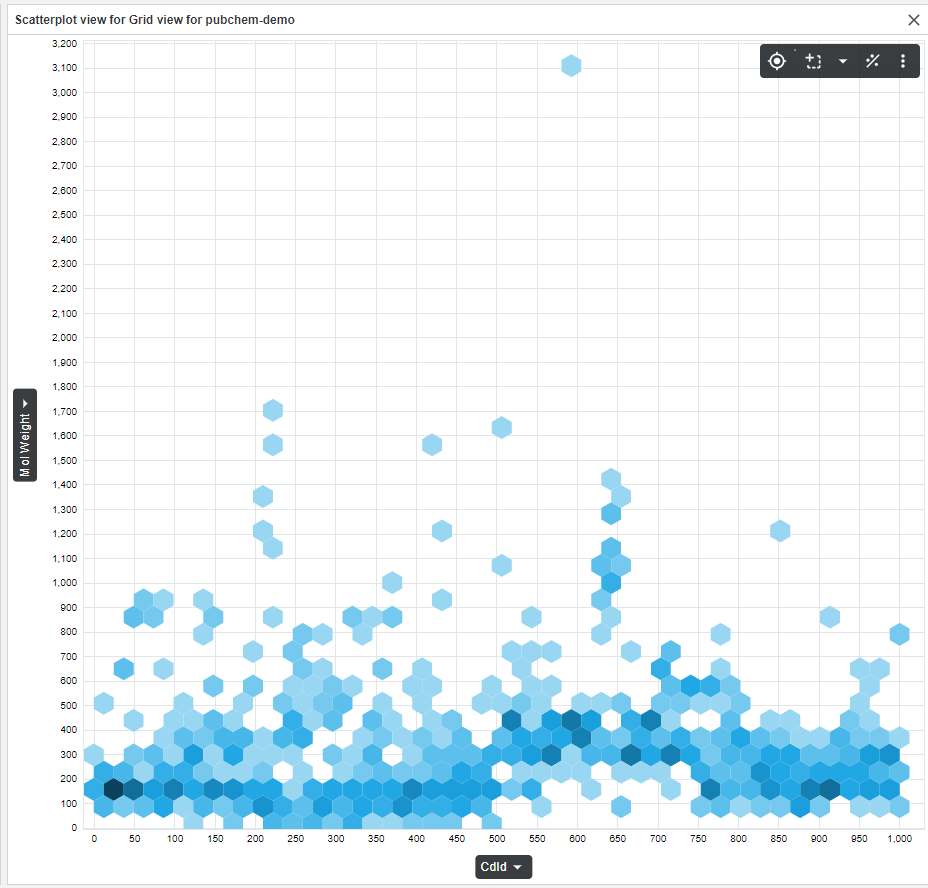
To enhance usability and performance, large data sets are initially displayed as hexbins which represent clusters of data points. The lightness of the hexbins corresponds to point density - the lighter the hexbin, the fewer data points it represents. After zooming in (thus decreasing the number of displayed data points) the hexbin view switches to a view which displays separate data points.
The default hexbin view can be switched off in the menu on the legend panel so even big data sets can be displayed as individual data points. Please note that the big data sets displayed as data points lack some functionalities compared to the hexbin view. The panning, zooming and screen reader functionalities are disabled.
Screen Reader (Crosshair)
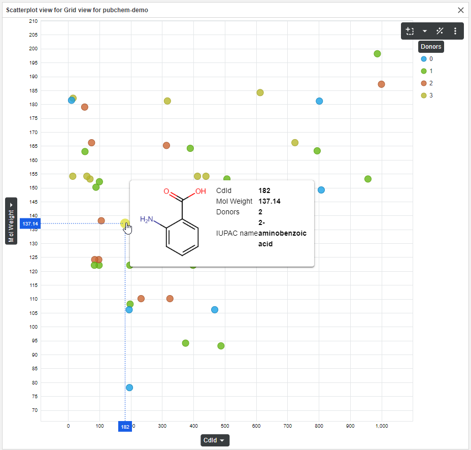
The Screen Reader (Crosshair) makes the position of a data point better readable. When the user hovers on a data point, the Screen Reader (Crosshair) displays the corresponding coordinate values on x and y axes. This functionality can be turned on and off in the menu on the legend panel.
Cards
This option offers an advanced way to visualize properties of a molecule in the chart. By hovering on a data point, properties of the related molecule appear on the Card. By default, these properties include the values displayed on the chart (x axis dimension and value, y axis dimension and value, dimension and value of the field selected for datapoint coloring). Additional fields can be selected in the first step of chart creation. Below the dropdown menus for x and y axes field selection, the properties displayed in the card can be selected by clicking on the corresponding fields in Additional fields section. Worth noting, the molecule structure can be also displayed this way on the Card. Displaying of a structure and relevant properties on the Card can be helpful to discover your molecules and their characteristics in the context of other molecules visualized in the same chart.
Box plot
This option can summarize information from classic scatter plot into box plot chart. Box plot can be switched on in the menu on the legend panel.
Histogram specific options
Cumulative curve
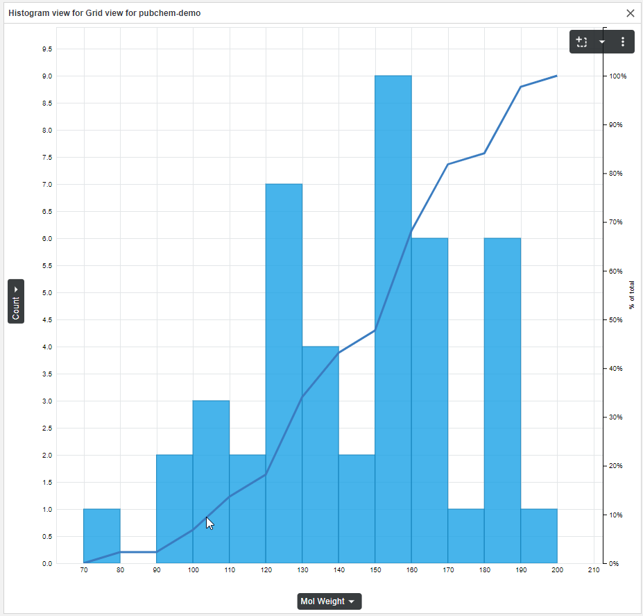
A cumulative curve of the percent distribution of the data points can be displayed by clicking the corresponding option in the menu on the legend panel. A separate vertical axis showing the percent distribution appears on the right side of the histogram.
Radar chart specific options
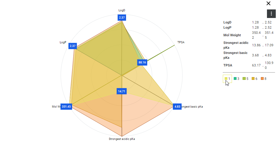
Multiple properties of a small number of rows of data can be visualized and compared on a radar chart. At least three fields (quantitative variables, e.g. molecule properties – logD, logP, TPSA) must be chosen for visualization. They are then represented on radially arranged axes. The chart contains equi-angular spokes and each spoke represents one of the variables. The length of a spoke is proportional to the value of the variable. The radar chart is plotted by the line connecting the data values of each spoke. The area defined by the chart (a star-shaped figure) represents an observation and reflects the similarity and variability of the values belonging to the selected rows. To make the chart easier to read, concentric circles serve as grid lines and the areas representing the selected rows are colored by different semi-transparent colors. As the areas overlap, only a small number of rows (<10) is recommended to visualize on a chart. The legend panel contains the minimum and maximum value of each variable and a list of colors which identify areas (rows) visualized on the chart. By clicking a color, the corresponding area is highlighted, and the values of variables become visible on the spokes.
Administration
Charts integration and related functionalities can be enabled / disabled by Plexus Connect administrator using PLEXUS_CHARTS business flag available in the featureFlags.properties file by setting the property to true or false, respectively. The changes will take effect the next log-in to Plexus Connect.