How the Instant JChem items fit together
Understanding organisation of the things you use in IJC is important. This includes:
-
What belongs to what. e.g. the parent - child relationships of the IJC artifacts.
-
Who owns what. e.g. what belongs to a user and what is shared amongst all users.
The related IJC Terminology document provides as brief definition of the different artifacts, while this document provides a more complete description of how it all fits together.
IJC is primarily a database based application, so lets start in the database and work upwards.
The IJC schema
The highest level concept in IJC is the SCHEMA. An IJC schema represents a connection to a database (e.g. a connection made to the database using a particular username and password). This could be a local database running within IJC or a remote database somewhere on your network (e.g. Oracle or MySQL). Within that SCHEMA are potentially all the database artifacts that are accessible from that connection. This will not always be the entire contents of the database.
The term SCHEMA used in the IJC context is not to be confused with the database concept of a schema, that is present in some databases like Oracle.
IJC entity and field
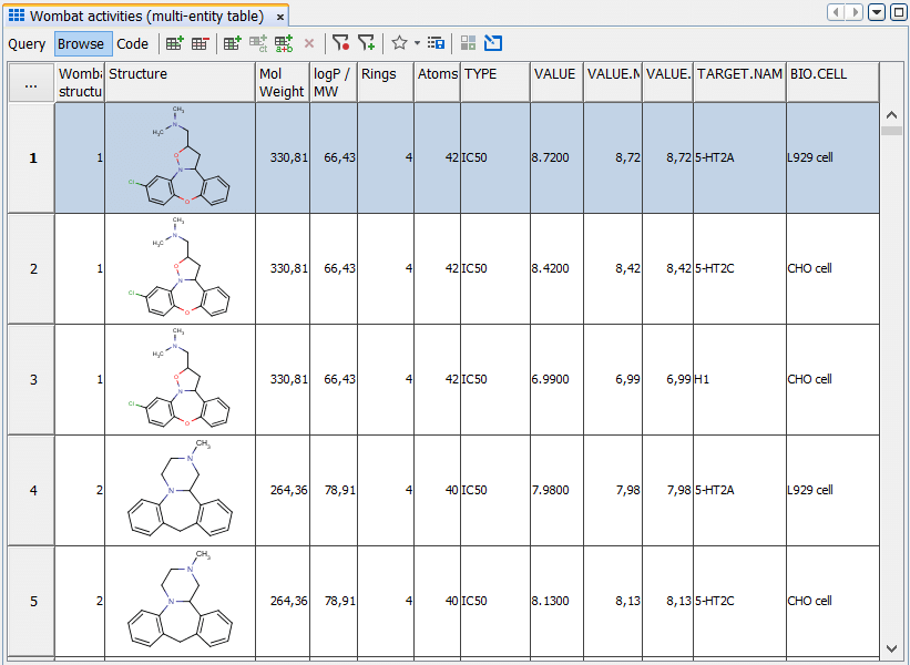
The database contains TABLEs and those tables contain ROWs and COLUMNs. When everything is set up in IJC you can see the data from such a TABLE in the IJC grid view in a way that is quite analogous to how it is organised in the database. However if IJC just provided a simple view of the raw data in the database it would look like it does in a database management tool. e.g. like this:

rather than this:

So IJC needs to transform this data in the database into something more suitable for the scientist to use, and it is the use of the ENTITY and the FIELD that allows IJC to do this.
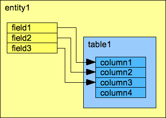
ENTITIES and FIELDs are IJC's representations of the database TABLEs and COLUMNs. They are similar to the TABLE or COLUMN but not identical. In the simple case an ENTITY is IJC's representation of a single TABLE and a FIELD is IJC's representation of a single COLUMN within a table. However the ENTITY and FIELD concept is broader in concept so that an ENTITY could be composed of multiple TABLEs and a FIELD could be composed of multiple COLUMNs. This can be very useful in providing a simplified or enhanced representation of the database. Examples of the differences between ENTITY/TABLE and FIELD/COLUMN are:
-
A JChem structure table. The multiple TABLEs that are used by JChem into a single ENTITY (up to four tables in the case of JChem cartridge).
-
Many irrelevant columns, such as the fingerprint columns of a JChem TABLE are not incorporated into the ENTITY, thus greatly simplifying what the user sees.
-
FIELDs can have additional display characteristics which are not defined at the level of the database column. For instance structures and text strings are both defined in the database in the same way, but need to be displayed very differently.
-
A FIELD with more complex behaviour, such as range fields (e.g. 100 - 110, or >63.4) can be handled correctly if the FIELD uses multiple columns (e.g. one for the min and one for the max value). Note: this type of FIELD is not yet implemented in IJC, but when this is done it will search and sort as expected, which is a major deficiency of most software handling this type of data.
-
The exact database column implementation can be hidden to the IJC user, for instance allowing them to specify that a FIELD should be for integer numbers, and not have to worry about the exact column type in the database.
As we can see, an ENTITY and a TABLE are somewhat similar, but distinct things. It is best to think of these not as different representations of the same thing, but as the ENTITY owning the TABLE, and the FIELD owning the COLUMN. Of course, the ENTITY also owns its own FIELDS, and hence, indirectly, the COLUMNs that belong to the TABLE.

There are currently two types of ENTITY in IJC, one for structures and one for "normal" data. There are multiple types of FIELD, generally corresponding to different data types (structure, integer, text, date etc.). The way these data types are implemented in the database (e.g. VARCHAR vs VARCHAR2 vs CHAR vs CLOB vs BLOB columns) is hidden to the IJC user.
Not all TABLEs and COLUMNs will be present in IJC as ENTITIES or FIELDs. Sometimes this because they are of no use to the user (for instance the fingerprint columns of a JChem table). However, when connecting to a database that already contains TABLEs, the TABLEs that are needed to be used (and their COLUMNs) will need to have their corresponding ENTITIES and FIELDs created. In IJC this process is called "promotion" and can be done in the Schema Editor. This allows IJC to easily connect to an existing database and use the TABLEs already in that database.
As an ENTITY owns the TABLE (or TABLES), when you delete the ENTITY it would be normal to also delete the TABLE. However, IJC lets you specify whether you want this to happen, and you can choose not to delete the TABLE if you wish it to remain in the database. A similar thing applies to deleting FIELDs and their COLUMNs.
IJC Relationships
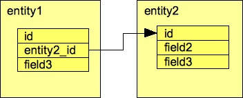
The next type of item to explain is the RELATIONSHIP and how it is related to a FOREIGN KEY CONSTRAINT in the database. A RELATIONSHIP defines how data in two ENTITIES is related. Rows in ENTITY 1 can be related to rows in ENTITY 2, and how this is done is defined by a RELATIONSHIP. RELATIONSHIPs have an ordinality that defines how the rows are related, and this ordinality can be:
-
one-to-one - meaning one row in ENTITY 1 is related to no more than one row in ENTITY 2
-
many-to-one - meaning many rows in ENTITY 1 can be related to a single row in ENTITY 2
-
many-to-many - meaning many rows in ENTITY 1 are related many rows in ENTITY 2
The one-to-many type also exists, but is really the same as the many-to-one when viewed from the other direction.
The equivalent thing in a database is a FOREIGN KEY CONSTRAINT. A RELATIONSHIP should be thought of as IJC's representation of a FOREIGN KEY CONSTRAINT in the same way that the FIELD is IJC's representation of a COLUMN.

There are some differences between a RELATIONSHIP and a FOREIGN KEY CONSTRAINT:
-
A RELATIONSHIP in IJC is visible from both ends (ENTITY 1 and ENTITY 2) whereas the FOREIGN KEY CONSTRAINT belongs only to one of the two database tables that are involved. Actually the RELATIONSHIP does know which ENTITY it belongs to, but it is displayed by, and know to both ENTITIES.
-
In the case of a many-to-many RELATIONSHIP IJC hides the join table that the database needs to handle this (many-to-many relationships in the database cannot be handled by a single FOREIGN KEY CONSTRAINT, but instead need a third table between the two tables and a FOREIGN KEY CONSTRAINT from this join table to each of the other tables. IJC hides all of this complexity and makes it appear that there is a direct many-to-many RELATIONSHIP between the two ENTITIES.
-
A RELATIONSHIP in IJC can be present without there needing to be a FOREIGN KEY CONSTRAINT in the database. This is not usually recommended, but can be useful in some cases. If this approach is taken referential integrity at the database level is not enforced (e.g. you can end up with "zombie" rows that don't belong to anything).
The IJC Data Tree
So far the ENTITY, FIELD and RELATIONSHIP in IJC allow the definition of how data is defined in the database and how one bit of data is related to another bit. However it does not really define how this data is to be used by the user. For example, let's assume we have some structures in a structure ENTITY and some assay results in an assay ENTITY and we have a many-to-one RELATIONSHIP between the two, so that each structure can have multiple assay results. This exact scenario is present in the Wombat data that is contained in the IJC demo project that you can open in IJC.
The problem here is that although the basic arrangement of the data is defined, the way the data wants to be visualised is not. For instance in is not yet clear whether the data wants to be viewed as a one-to-many master detail report from the perspective of the structures, or a many-to-one report from the perspective of the assay results. Both are perfectly valid and sensible, and if more than two ENTITES and one RELATIONSHIP are involved then the number of alternatives can explode.
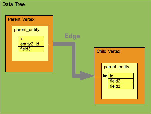
The IJC DATA TREE addresses this issue. The DATA TREE defines the master detail arrangement of ENTITIES according to the RELATIONSHIPS between those ENTITIES. Multiple DATA TREEs can be created with alternative arrangements of the ENTITIES, and the Wombat demo data contains both of the arrangements described above. For those of you familiar with ISIS/Base the DATA TREE is more or less analogous to the ISIS Hview. A tree-like structure is not the only way of representing data like this, but is certainly the easiest for users to understand.
A DATA TREE always has a single ENTITY as its parent element. Many DATA TREEs contain just this, and are referred to as simple DATA TREEs. When the parent element contains one of more child elements the DATA TREE is referred to as a complex DATA TREE. When a child element is added to a parent element it is done using a RELATIONSHIP that exists between the two ENTITIES. In technical terms the elements in the DATA TREE are referred to as VERTEXes and the associations between them as EDGEs, but you rarely need to use this terminology, and they really represent the ENTITY and RELATIONSHIP that they use.

One key thing to understand about a DATA TREE is that it uses its ENTITIES and RELATIONSHIPS rather than owns them. This is a key distinction as an ENTITY or RELATIONSHIP can belong to multiple DATA TREE (see the Wombat example).
The uses rather than owns nature of the DATA TREE, along with the fact that multiple DATA TREEs can use the same ENTITIES and RELATIONSHIP has a number of important consequences that are important to understand:
-
Think of the question "What should happen when I delete the DATA TREE?". In the Wombat example it would clearly be wrong to delete the ENTITIES and RELATIONSHIPs involved as they are still used by a different DATA TREE. Consequently the contents of a DATA TREE are not automatically deleted when you delete the DATA TREE. They remain present so that they can still be used in different DATA TREES or can be added to a new DATA TREE. However, in the special case of an ENTITY only being used by the DATA TREE that is being deleted IJC will give you the option of also deleting the ENTITY should you with to do this.
-
Adding a RELATIONSHIP will not automatically add the corresponding EDGE to the DATA TREE. You might have multiple DATA TREES, and it is not clear which ones you want to update. You must specify yourself by modifying each DATA TREE as appropriate.
-
Similarly, deleting an EDGE from a DATA TREE will not delete the underlying RELATIONSHIP.
-
If an ENTITY or RELATIONSHIP is deleted the corresponding items will be removed from all DATA TREEs that use that ENTITY or RELATIONSHIP (contrast this with deleting the DATA TREE). The way the DATA TREE is defined is very important to understand if you want to make effective use of relational data in IJC. If you are not clear on this then please re-read this section!
IJC Views: form view and grid view
Up to now all items (SCHEMA, ENTITY, FIELD, RELATIONSHIP, DATA TREE, VERTEX, EDGE) are shared between all users. Effectively they are owned by IJC. If they are modified (and you can only modify them if you have sufficient access rights) then the changes apply to all users as they are using the same shared item.
For views things are different, as each user will want to have their own particular forms. Thus views, whether they be form views or grid views belong to the individual user, and one user's views are completely separate from those of a different user (however views can be shared, but we'll come on to that in a sec.). This allows each user to define their own views, and to use them as they choose.
IJC Queries and Lists
Similarly to views, queries and lists also belong to the individual user. When you execute a query the query definition and the hit list are saved to your personal set of queries and lists.
Sharing Views, Queries and Lists
As mentioned, views, queries and lists belong to the individual user. However, they can be shared amongst all users if the owner desires. In this case other users will also see those items and can use them. They will appear by default for all users if shared. However, only the owner of the item can make changes as the owner will not want others to make changes to their own items. This can be problematical, as even the most trivial change is still a change, and this can be as simple as changing the width of a column in the grid view, and clearly it would be very restrictive if this was not allowed. To resolve this there are 2 approaches that are possible:
-
Take a copy of the item so that the copy is now yours, and you can do what you want with it. If you do this you will not then see any subsequent changes to the original. This is available for views, lists and queries.
-
Make changes to the item, but those changes are only transient and will not be saved, so that the original is not affected. This approach only applies to views.
Summary
To make best use of IJC, particularly in a multi-user environment when using relational data it is important to understand how the different pieces fit together. Hopefully this will be much clearer now!